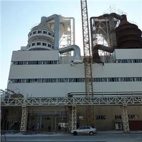
A caustic soda plant based on the chlor-alkali process is not a single machine but a continuous electrochemical production system. Each section of the plant performs a specific transformation or purification step.
Brine Preparation System
The brine preparation system converts solid industrial salt (NaCl) into saturated brine suitable for electrolysis feed. In most membrane chlor-alkali designs, the target brine concentration is controlled at approximately 300–310 g/L NaCl.
The system typically includes a salt dissolving tank, agitators, coarse filtration screens, and a brine circulation loop. The dissolution tank is designed to maintain a controlled residence time, usually 2–4 hours, to ensure complete dissolution of sodium chloride crystals.
Undissolved impurities such as sand, clay, and insoluble salts are removed through settling or hydrocyclone separation. The output brine is then transferred to the purification section.
The design of this subsystem is directly related to membrane cell life, since suspended solids above 1 mg/L can accelerate membrane fouling and increase cell voltage over time.
Brine Purification Unit
The brine purification system removes divalent cations such as calcium (Ca²⁺), magnesium (Mg²⁺), and trace heavy metals that interfere with membrane performance. In membrane chlor-alkali systems, calcium and magnesium concentrations must typically be reduced to below 20 ppb (parts per billion).
The standard purification method is chemical precipitation using sodium carbonate (Na₂CO₃) and sodium hydroxide (NaOH). The reactions form insoluble calcium carbonate and magnesium hydroxide:
Ca²⁺ + CO₃²⁻ → CaCO₃↓
Mg²⁺ + 2OH⁻ → Mg(OH)₂↓
These precipitates are removed using clarifiers or lamella sedimentation tanks followed by fine filtration systems, typically 5–10 micron cartridge filters.
Polishing filters are installed downstream to ensure stable feed quality to electrolyzers. The brine purification system also includes pH control loops and ORP monitoring to maintain reaction efficiency.
Electrolyzer System (Membrane Cell Section)
The electrolyzer is the core of the chlor-alkali process. Modern plants use ion-exchange membrane cells, typically based on perfluorosulfonic acid (PFSA) membranes.
Each electrolyzer cell is divided into an anode compartment and a cathode compartment separated by a cation-selective membrane. Brine is fed into the anode chamber, where chloride ions are oxidized to chlorine gas:
2Cl⁻ → Cl₂ + 2e⁻
At the cathode side, water is reduced to hydrogen gas and hydroxide ions:
2H₂O + 2e⁻ → H₂ + 2OH⁻
Sodium ions migrate through the membrane and combine with hydroxide ions to form sodium hydroxide (NaOH).
Typical operating parameters for industrial membrane cells include:
Cell temperature: 85–95°C
Current density: 3.0–6.0 kA/m²
Cell voltage: 3.0–3.3 V
NaOH concentration: 30–35 wt% (cell liquor output)
The electrolyzer system includes cell frames, electrodes (titanium anode with ruthenium/iridium coating), nickel cathodes, and hydraulic sealing systems. Cell alignment and compression force are controlled to prevent leakage and maintain membrane integrity.
Rectifier System
The rectifier system converts AC power from the grid into DC power required for electrolysis. Chlor-alkali plants typically operate at very high DC currents, often in the range of 10 kA to 200 kA depending on plant capacity.
The rectifier is composed of:
Transformer unit (step-down and isolation)
Thyristor or IGBT rectifier modules
DC busbars
Cooling system (air or water-cooled)
Output voltage is typically between 100 V and 600 V DC depending on stack configuration. Current ripple is controlled below 5% to maintain stable electrochemical reaction conditions.
Power factor correction systems are often integrated to maintain grid compliance, especially in large-scale plants exceeding 50,000 tons/year NaOH capacity.
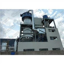
Evaporation System
The evaporation system increases NaOH concentration from approximately 30–35% (electrolyzer output) to commercial grades such as 48% or 50% caustic soda solution.
Multi-effect evaporation (MEE) is commonly used to reduce steam consumption. A typical configuration includes 2 to 4 evaporation effects operating under decreasing pressure.
Steam input is usually at 3–6 bar saturated steam depending on plant design. Vacuum levels in later stages are maintained around -0.08 to -0.09 MPa to improve thermal efficiency.
The evaporator materials must resist strong alkaline corrosion at elevated temperatures, so nickel-based alloys or special stainless steels (such as 316L or duplex grades) are commonly used.
Chlorine Handling System
Chlorine gas produced in the electrolyzer is wet, hot, and contains traces of hydrogen and brine mist. Before downstream use or liquefaction, it must be cooled and purified.
The chlorine handling system includes:
Gas cooling tower (reduces temperature to ~35–40°C)
Mist eliminators (remove entrained droplets)
Chlorine drying system (using sulfuric acid or adsorption dryers)
Compressors (for liquefaction or pipeline transfer)
Dry chlorine purity is typically controlled above 99.5% for industrial use. Moisture content is reduced below 30 ppm to prevent corrosion in downstream equipment.
Materials in chlorine service are selected based on corrosion resistance, commonly including titanium, PVC-lined steel, or FRP piping.
Hydrogen Recovery System
Hydrogen generated at the cathode is typically saturated with water vapor and contains traces of caustic mist. The recovery system performs separation, cooling, and compression.
The system includes:
Gas-liquid separator
Demister unit
Cooling heat exchanger
Hydrogen compressor (diaphragm or screw type)
Optional purification unit (PSA or catalytic polishing)
Hydrogen purity after separation typically exceeds 99%. Dew point control is critical to prevent condensation in pipelines.
In many industrial installations, hydrogen is either:
used as fuel in boilers or steam systems
or exported to chemical synthesis processes such as ammonia or methanol production
Automation System (PLC/DCS)
The control system integrates all process sections into a single coordinated operating platform. Most modern chlor-alkali plants use distributed control systems (DCS) combined with programmable logic controllers (PLC) for equipment-level control.
Key control loops include:
Brine concentration control (conductivity-based)
Electrolyzer current regulation
Cell temperature control (via brine circulation)
NaOH concentration monitoring (density measurement)
Chlorine pressure control
Hydrogen pressure and flow regulation
Typical instrumentation includes:
conductivity sensors (0–300 mS/cm range)
pH analyzers (0–14 scale)
differential pressure sensors across membranes
flow meters (electromagnetic or Coriolis type)
gas analyzers for chlorine and hydrogen purity
Data acquisition is typically recorded at 1–5 second intervals depending on system design. Alarm interlocks are implemented for chlorine leakage detection and hydrogen overpressure conditions.
A caustic soda plant is designed as a continuous loop system where raw salt is converted into three product streams: sodium hydroxide, chlorine, and hydrogen. The operational stability of the plant depends on maintaining feed brine purity, stable DC current distribution, and controlled thermal balance in both electrolysis and evaporation sections.
Any deviation in brine impurity levels or rectifier instability directly affects membrane voltage and reduces system efficiency. Therefore, most engineering designs prioritize upstream purification and downstream gas handling reliability as much as the electrolyzer itself.
Conclusion (Engineering Summary)
From a process engineering perspective, a caustic soda plant is a tightly integrated electrochemical system composed of chemical preparation, electrolysis, power conversion, thermal concentration, gas handling, and automation layers.
Each subsystem has measurable operating parameters, and plant performance is determined by the stability of these parameters rather than any single equipment unit.
The overall design philosophy is based on three constraints:
ionic purity of feed brine
electrical efficiency of membrane electrolysis
safe separation and handling of chlorine and hydrogen
These constraints define the configuration of all major equipment in a modern chlor-alkali installation.